Development
of an electrolytic stabilisation method, for
aluminium alloy remains from aircraft wrecks
By Christian Degrigny
•
Introduction • General corosion
data • Results of the project
• Definition of parameters •
Pitting corosion • Cathodic
corosion
• Development of a safe treatment
• References
Abstract
Metal artefacts recovered from marine or any other
underwater site are usually highly damaged due to the corrosion processes
taking place in
the aqueous environment. When lifted and left to dry outdoor these artefacts
are exposed to the aggressive action of both the oxygen and the water
of the atmosphere and new corrosion processes occur. This corrosion is
activated by aggressive species contained in the materials such as chlorides
from the environment. An electrolytic stabilisation treatment has been
designed
to extract these aggressive species.
The protocol defined has been first applied in the 90s on aircraft remains
from Biscarrosse lake. Situated in the South-West of France, this lake
saw considerable use between the two world wars for air traffic by seaplanes
between France and South America. During the 2nd world war the Germans
used the base and due to the numerous attacks there, many wrecks both
French and German have been found. In particular
a giant Luftwaffe Blohm & Voss BV222.
Introduction
Metal artefacts recovered from marine or any other underwater site are
usually highly damaged due to the corrosion processes taking place in
the aqueous environment. In some cases such as for large iron artefacts
a superficial crust has formed with time and has slowed down the alteration.
When lifted and left to dry outdoor these artefacts are exposed to the
aggressive action of both the oxygen and the water of the atmosphere and
new corrosion processes occur. This corrosion is activated by the aggressive
species contained in the materials such as chloride species or metallic
impurities.
Aluminium alloys are the characteristic materials of modern wrecks. Produced
industrially at the beginning of the 20th century, they have been since
the major structural materials of aircrafts. Aircraft remains are found
everywhere, buried in the ground, all along the coasts or in lakes like
at Biscarrosse (figure 1). This lake situated in the South-West of France
has been considerably used between the two world wars for the air traffic
by seaplanes between France and South Africa. During the 2nd world war
the Germans used the base and due to the numerous attacks there, many
wrecks both French and German have been found.
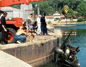
Figure 1: Remains of an engine from a Blohm and Voss 222. Biscarrosse
lake
– France (courtesy of R. Bertholon)
No crust is found on aluminium alloys from underwater environments. According
to their composition the corrosion is more or less developed. Corrosion
processes are more problematic when the alloy contains copper as an additional
element. Since aircraft structures contain many other metals than aluminium
alloys (copper, steel magnesium alloys) galvanic processes occur between
all of them when they are associated to each other. Thus iron and steel
compounds are protected at the expense of aluminium alloys which corrode
(figure 2).
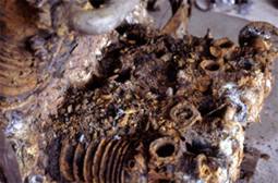
Figure 2: Detail of the engine of a CAMS 37 recovered from Biscarrosse
lake.
The aluminium-copper cylinder heads are highly damaged and have protected
the steel elements during immersion
The objective of this Ph.D. research was to concentrate on the stabilisation
(extraction of aggressive species) of aluminium alloys impregnated with
chloride salts. The technique considered is based on cathodic polarisation.
The object is connected to the negative terminal of a power supply (figure
3) and a constant cathodic potential is applied. The process is more efficient
(faster) than just immersion. Our task has been to define the appropriate
parameters for the treatment since side effects (described later) might
appear otherwise.
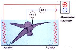
Figure 3: general device for the electrolytic stabilisation of a propeller
from the BV222.
General data on the corrosion of aluminium alloys -
Top
In the atmosphere aluminium and its alloys are always covered with an
oxide film due to the strong affinity of aluminium for oxygen. This film
is highly protective in the case of pure aluminium. The presence of additive
elements (Cu) in the metal creates defects and decreases its protective
effect.
When immersed in an underwater environment, the film formed might change
according to its aggressiveness. In almost pure neutral water, the oxide
film becomes thicker (10 to 100 times). In aggressive waters (containing
chlorides, metallic cations, acid or basic), it might dissolve. The film
is indeed stable in solutions which pH is comprised between 4 and 9.
Pitting corrosion occurs when the aqueous environment contains aggressive
anions (chlorides, sulphates or nitrates). The mechanism is divided in
2 steps. First the passive oxide film is dissolved due to the interaction
with the aggressive species. This reaction usually takes place at “active”
sites (Al2Cu or Al3Fe inclusions). Secondly the aluminium material underneath
reacts strongly with the species and creates a pit. The tip of the pit
is the anode of a galvanic cell and the top of the pit is the cathode
(see figure 4).
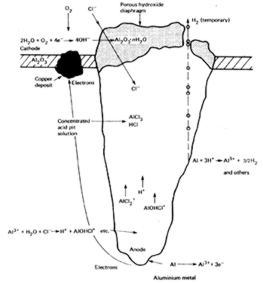
Figure 4: Schematic diagram of active corrosion
pit in aluminium
These electrochemical reactions are quite complex
but to simplify, we can propose the following half reactions:
- at the tip of the pit (anode): Al ‡ Al3+ + 3e- (1)
- at the top of the pit (surface of the metal): 2H2O + O2 + 4e- ‡
4OH- (2)
The electrons are transferred through the metal. Both Al3+ and OH- react
together to form an Al(OH)3 deposit (white powder or gel formed locally
on the surface of aluminium alloys and often observed on underwater remains).
Al3+ cations that are dissolved in the pit react with water and chloride
species to acidify the inside of the pit according to the following reaction:
Al3+ + H2O + Cl- ‡ H+ + AlOHCl+ (3)
To maintain the same level of electronic charge in the pit, more chlorides
diffuse from the environment to the inside of the pit which then expands
due to the corrosion processes developed.
Since Al can react directly with H+ and Cl- another reaction can take
place:
Al + 3H+ + 2Cl- ‡ 3/2H2 + AlCl2+ (4)
H2 is then produced and fragilises more the oxide film protecting the
surface.
Typical pH obtained inside the pit is around 3,5. Similar phenomena occur
in the presence of nitrates and sulphates but the corrosion is much slower.
When chlorides are mixed with high concentrations of nitrates or sulphates,
these latter anions might play an inhibitive role.
Practically pitting corrosion occurs above a certain potential (Ep). Ep depends on the composition of the alloy and the concentration of aggressive species. Figure 5 shows an exhaust pipe from a Blohm and Voss 222 engine made in aluminium-manganese alloy and damaged by pitting corrosion.
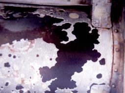
Figure 5: Shows typical hemispheric pits formed on an aluminium-
manganese exhaust pipe from a Blohm and Voss 222.
Intergranular corrosion appears often on aluminium-copper alloys
due to the presence of Al2Cu inclusions at the grain boundaries.
The corrosion starts as a pitting corrosion and develops then along the
grain boundaries due to the difference of potentials between
the inclusions (cathode) and the grains (anode). When the metal has been
laminated, exfoliation might occur (figure 6).
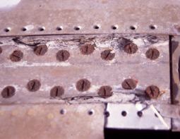
Figure 6: typical exfoliation corrosion on a fuselage element
made in aluminium-copper alloy
Cathodic corrosion
This is a particular corrosion process that occurs when the potential
of the aluminium alloy is decreased to lower values (cathodic polarisation).
It can happen when the metal is connected to a more reductive metal (like
magnesium) creating then a galvanic cell. It corresponds to a local or
general dissolution of the metal. Mechanisms are different according to
the nature of the environment. In a non-buffered and neutral solution
(non stable pH) local alcalinisation (increase of pH) may occur. The oxide
film dissolves then locally. Usually this corrosion is initiated at “active”
sites. These “active” sites correspond once again to metal inclusions
such as Al2Cu and Al3Fe. Once the oxide film is removed, the site becomes
very reactive. The aluminium matrix around the inclusion corrodes, a bubble
of hydrogen usually forms (reaction (1) favoured) and activates locally
the process. At the end the inclusions are released and the activity ceases
due to the formation of a new protective film in the pit formed. If the
potential of the aluminium alloy is too negative, the local pH is too
high and the dissolution continues. A general corrosion occurs then. In
a buffered and slightly acid solution, a local alcalinisation cannot occur.
In this case the corrosion is due to the diffusion in the protective film
of H+ species that hydrate it. This hydration provokes a decrease of the
protection. If the potential of the aluminium becomes more negative the
film thickness is reduced and cathodic corrosion might take place (figure
7). Again the corrosion usually starts at “active” sites.
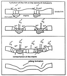
Figure 7: mechanism of cathodic corrosion of aluminium
alloys in a buffered solution
Practically cathodic corrosion appears at a certain negative potential
(breakdown potential Erl). Erl depends on the pH: the higher it is, the
less negative Erl is. It depends too on the composition of the alloy (amount
of “active” sites). Below a certain potential (Er) the cathodic
corrosion is no more local but is general.
Results of the research project - Top
The materials considered for the project came from German seaplanes dating
from the last world war. These Blohm and Voss 222 sank in Biscarrosse
lake in 1942. 3 different aluminium alloys were studied: 3003 (aluminium
- manganese 1%) from exhaust pipes, 2014 (aluminium - copper 4% - Magnesium
0.5% - Silicon 0.5% - Manganese 0.5%) from the fuselage and 6082 (aluminium
– Magnesium 0.9% - Silicon 1% - Manganese 0.7%) from the propellers
cover. Figure 8 shows the remains where these alloys were sampled. Each
alloy had been heat treated in a specific way to get the required mechanical
characteristics (T6 for 2014, T4 or T6 for - 6082 and H26 for 3003). Figure
5.
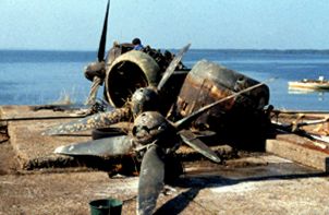
Figure 8: some of the remains from a Blohm and Voss 222.
Biscarrosse lake. (Courtesy of R Bertholon)
Biscarrosse water is almost freshwater. The pH is between 6.3 and 6.9.
The amount of cations is quite small (Ca2+ + Mg2+: 9.6ppm, Na+ + K+: 11.8ppm)
as well as the amount of anions (Cl-: 28.2ppm and SO42-: 11.9ppm). Nevertheless
the chloride amount is enough to provoke pitting corrosion.
Instability of the alloys when
exposed to the atmosphere
The alloys considered were documented once recovered from their environment.
They were suffering from different corrosion processes.
- 2014: pitting corrosion, intergranular corrosion (figure 9) and exfoliation
- 3003: pitting corrosion and traces of intergranular corrosion
6082: pitting corrosion only (figure 10)
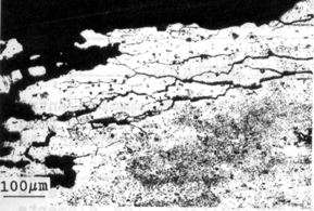
Figure 9: cross-section of a laminated 2014 alloy showing typical
intergranular corrosion
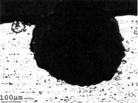
Figure 10:cross-section of a 6082 alloy showing typical
hemispheric pit
These alloys suffered too from galvanic corrosion when they were attached
to iron parts. Some other remains attached to magnesium elements had been
cathodically protected. Cathodic corrosion might have occurred then.
Different analysis of the corrosion products were conducted. Al(OH)3 was
identified by X-ray diffraction. X fluorescence analysis showed that chlorides
were present at the tip of the pits and copper species were polluting
superficial corrosion products in the case of 2014 alloy.
To determine how stable these materials could be in the atmosphere two
experiments were conducted: plates of these alloys were exposed 1 year
at Biscarrosse site on a specific frame (figures 11 and 12). Both cleaned
and corroded plates were considered.

Figure
11: corroded aluminium plates (cleaned or not)
sampled from Blohm and Voss 222 elements and prepared
for corrosion test at Biscarrosse site
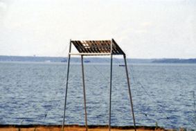
Figure 12: the frame at exposure at Biscarrosse site
The second experiment
was conducted in a humid chamber (cycles of 2h at 100%HR and 25C followed
by 2h in a dry atmosphere at 40C).
Once conducted the plates were observed on cross-sections. For both experiments
2014 developed a strong intergranular corrosion and exfoliation trend
(figure 13). 3003 and 6082 were less reactive but still some new corrosion
phenomena appeared proving then the need of a stabilisation treatment
to conserve in the long term these materials.
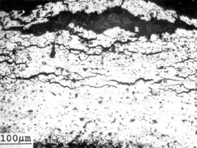
Figure 13: exfoliation observed on corroded 2014 alloy exposed
1 year at Biscarrosse site
The definition of the electrolytic parameters
- Top
To
treat electrolytically a metal artefact it is important to determine first
the field of potentials where the metal is stable. In corrosion science
we usually refer to the potential-pH diagram of aluminium (figure 14)
which indicates that aluminium is covered with Al(OH)3 or Al2O3 in neutral
solutions (pH between 4 and 9). In between the two diagonals a/ and b/
the aqueous solution is stable. Above it is decomposed in oxygen;
underneath in hydrogen.

Figure 14: potential-pH
diagram for aluminium in pure water
commonly called Pourbaix diagram. Potentials are given versus
SHE.
During the cathodic polarisation, aluminium alloys can be
damaged by two processes: pitting corrosion and cathodic
corrosion. Pitting corrosion can be provoked by chloride anions
extracted in the solution.
Pitting corrosion - Top
The risk of pitting corrosion has been assessed by the determination of
the pitting potential (Ep) under which no pitting can occur. Ep is not
a reproducible value. We can only estimate it. In corrosion science we
prefer to talk of the probability of pitting above a certain potential.
Two potentials are then defined: the potential of low (Ep inf) and high
probability (Ep sup). Above Ep sup, there is 100% probability that pitting
corrosion occurs on the metal considered.
This risk has been studied at different pH values using buffered solutions
(with citrate or borate ions) containing the amount of chlorides usually
extracted during stabilisation treatments (10-3M). It can be observed
on figure 15 that usually the pitting potentials are slightly higher for
a certain pH in between 4.2 and 9.
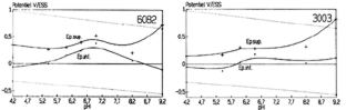
Figure 15: experimental potential-pH diagrams for 6082 and 3003
alloys between pH 4 and 9.
[NaCl]=10-3M. Potentials are given versus ESS
In all the cases we observed the trend: Ep3003 < Ep6082 < Ep2014.
Once these trends are known it is important to determine if the risk is
real. To get an answer clean plates of the 3 previous alloys were immersed
in a buffered solution containing 10-3M NaCl and the corrosion potential
Ecorr was monitored with time. Naturally Ecorr increased in the aerated
solution (passivation behaviour). Potentials corresponding to the entrance
in the area of risk of pitting corrosion are indicated on figure 16. It
appears that the risk is real after only a few minutes.
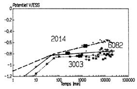
Figure 16: Monitoring of Ecorr of 3003, 6082 and 2014 alloys
versus time. pH=5.4, [NaCl]=10-3M. The potentials corresponding
to the entry in the field of risk of pitting corrosion are indicated
When we treat electrolytically an aluminium artefact such a risk of corrosion
is small. But in the case where a loss of electric contact occurs, this
risk becomes important, particularly in aerated conditions. As an illustration
we can see on figure 17 the surface of an aluminium-silicon alloy found
in Biscarrosse lake and immersed in deionised water for 4 months. Pitting
corrosion occurs.
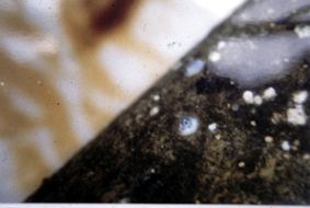
Figure 17: Apparition of pitting corrosion (under the white
efflorescence covered with an H2 bubble, on the surface of an
aluminium-silicon alloy recovered from Biscarrosse lake after
4 months of immersion in deionised water
Cathodic corrosion Top
As mentioned before cathodic corrosion might occur if a too negative potential
is applied to the aluminium alloy. Cathodic corrosion can be followed
on current-time plots. A cathodic potential is applied to the alloy and
the current density (current divided by the area of the artefact) is monitored
with time. Figure 18 shows such a curve for different aluminium alloys
in a buffered solution. First the current increases slowly and then quite
fast.
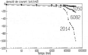
Figure 18: cathodic polarisation of different aluminium alloys
(1050 is almost pure aluminium) at a constant potential of –
1.4V/ESS in a buffered (pH=5.4), unstirred and non-aerated
solution. [NaCl]=10-3M
The corrosion increases with both the stirring and the aeration of the
solution. The corrosion depends a lot on the stirring and the aeration
of the solution and becomes more important when both are increased.
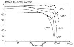
Figure 19: effect of the cathodic potential on the cathodic
polarisation of a 2014alloy in a buffered (pH=5.4), stirred and
aerated solution. [NaCl]=10-3M
The corrosion mechanism has been followed optically.
Figure 20 shows the results obtained. During the slow increase of the
current density the inclusions on the metal surface become more obvious
(from a to b). When a hydrogen bubble is formed and is trapped on the
surface, the corrosion is more developed underneath (b and c). Once the
process has started, the corrosion develops rapidly: the current density
increases and more corrosion is observed on the surface (d).
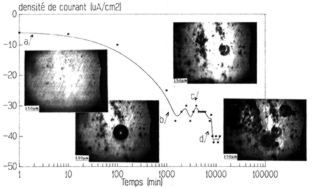
Figure 20: cathodic polarisation of a 2014 alloy at a cathodic potential
of –1.55V/ESS in a buffered (pH=5.4), stirred and non-aerated solution.
[NaCl]=10-3M.
Observation of the surface under a microscope is conducted in parallel.
As mentioned before the matrix is consumed during the corrosion process
and the inclusions are slowly released (figure 21). Once removed the corrosion
process stops locally. Practically the cathodic corrosion is characterised
by its breakdown potential (Erl). In buffered solution and for the alloys
considered only a potential provoking general corrosion has been defined.
For non buffered solutions only local corrosion might be observed.
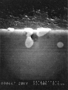
Figure 21: Cross-section of a 2014 alloy polarised
cathodically at –1.45V/ESS in a buffered (pH=5.4),
stirred and non-aerated solution. [NaCl]=10-3M.
Metallic inclusions are partly released.
The more “active” sites for a 2014 alloy are inclusions containing
Cu, Mn and Fe. Figure 22 shows that they become enriched with Cu during
the cathodic corrosion.

Figure 22: Modification of the composition of metallic inclusions
during the cathodic polarisation of a 2014 alloy in a buffered
(pH=5.4), stirred and non-aerated solution at –1.55V/ESS.
[NaCl]=10-3M. a/ before polarisation. b/ after polarisation.
For other alloys only the inclusions containing depolarising elements
such as Fe and Cu are “active”. The corrosion remains local
when the inclusions are uniformly distributed.
Development of a safe stabilisation
treatment - Top
Based on the previous results we are able now to construct modified potential-pH
diagrams for the aluminium alloys considered. Figure 23 shows such a diagram
for 6082 alloy.
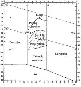
Figure 23: experimental potential-pH diagrams for 6082
alloy where the fields of pitting corrosion and cathodic
corrosion in neutral pH have been added. [NaCl]=10-3M
The stabilisation process can be applied in the field of potential where
the metal surface is passivated.
Like for copper and iron artefacts, the electrolytic stabilisation is
monitored by plotting the concentration of chlorides extracted versus
the square root of time. At the beginning of the process the curve should
follow a straight line which corresponds to a diffusion law. When the
concentration of chlorides extracted is below this straight line the solution
has to be changed. Several changes are usually needed to achieve a correct
stabilisation treatment.
I would like to thank Electricity of France which funded most of the work
done presented in this research project as well as the Foundation
TIGHAR (The Worlds s leading aviation archaeological foundation) for
its financial support in the treatment of the Pratt and Whitney engine
treated at the AWM. I thank as well the staff of the AWM Conservation
Annex for their help during the treatment of this engine.
References
Degrigny C., Mise au point d´un traitement cathodique de stabilisation
de pièces en alliages d´aluminium dégradées
par corrosion en milieu aqueux, thèse de doctorat de l´Université
de Paris VI, 1990.
Degrigny C., La mise au point d´un traitement cathodique de stabilisation
de vestiges aéronautiques immergés en alliages d´aluminium,
in Saving the 20th century: the conservation of modern materials, Ed.
D. Grattan, Ottawa (1993) 373-380. Top